Heat treatment of steel is one of the most important branches of materials engineering. It involves the deliberate heating and cooling of steel under controlled conditions in order to manipulate its internal structure and, as a result, its mechanical and physical properties. By carefully selecting the temperature ranges, holding times, and cooling rates, engineers can produce steels that are soft and machinable, extremely hard and wear resistant, or tough and fatigue resistant. This versatility makes heat treatment indispensable in industries ranging from automotive and aerospace to energy, construction, and tool manufacturing.
The scientific basis of heat treatment lies in the iron–carbon phase diagram and the transformation behavior of austenite. When steel is heated into the austenitic region, carbon atoms dissolve into the face‑centered cubic lattice of iron. Upon cooling, depending on the rate and the presence of alloying elements, this austenite can transform into pearlite, bainite, martensite, or mixtures thereof. Each of these microstructures has distinct hardness, strength, and ductility. For example, pearlite provides a balance of strength and toughness, martensite offers extreme hardness but low toughness, and bainite provides a compromise between the two.
The principles of heat treatment therefore revolve around three key variables:
In practice, heat treatment encompasses a wide range of processes. Annealing and normalizing are used to soften steel, refine grain size, and relieve stresses. Hardening by quenching produces martensite, which is then tempered to adjust hardness and toughness. More advanced methods such as austempering and martempering are designed to reduce distortion and improve toughness. Surface treatments like carburizing, nitriding, and induction hardening enrich or transform only the outer layers, producing a hard, wear‑resistant case with a tough core. Each of these processes requires precise control of parameters and a deep understanding of steel metallurgy.
This document will explore the subject in detail, beginning with the fundamentals of the iron–carbon system and transformation diagrams, then moving through the major processes of heat treatment, their microstructural outcomes, and their practical applications. It will also discuss common defects such as cracking, distortion, and decarburization, along with methods of quality control and inspection. Finally, industrial considerations such as furnace types, protective atmospheres, and safety practices will be addressed. The goal is to provide a comprehensive, print‑friendly reference that links theory with practice for students, engineers, and professionals working with steels.
Steel is an alloy of iron and carbon (often with additional alloying elements) whose properties are governed by phase transformations within the iron–carbon system. Understanding the phases that appear as temperature and composition change is essential for designing heat treatments. The principal phases—ferrite, austenite, and cementite—combine to form microstructures such as pearlite, bainite, and martensite. Each phase and microstructure has distinct crystal structures, carbon solubility limits, transformation mechanisms, and property implications.
Ferrite is the body‑centered cubic (BCC) form of iron stable at lower temperatures. It has a low solubility for carbon (on the order of hundredths of a percent at room temperature), which means carbon atoms occupy interstitial positions only sparingly. Ferrite is relatively soft and ductile, contributes to toughness, and is magnetic at ambient conditions. In hypoeutectoid steels (less than ~0.76% carbon), ferrite coexists with pearlite after slow cooling, and its volume fraction increases as carbon content decreases. Grain size of ferrite strongly affects yield strength and toughness; refining ferrite grains through normalizing or controlled rolling improves strength without excessively compromising ductility.
Austenite is the face‑centered cubic (FCC) form of iron stable at elevated temperatures. Its FCC lattice accommodates significantly more carbon in interstitial sites (up to ~2.1% near 1147°C), enabling solution treatment and homogenization during austenitizing. Austenite is non‑magnetic and generally tougher than ferrite at comparable temperatures. Most heat treatments begin by heating steel into the austenitic region (above Ac3 in hypoeutectoid steels or near Ac1/Acm in hypereutectoid steels) to dissolve carbides, equalize composition, and set the stage for subsequent transformations during cooling. The prior‑austenite grain size formed in this step critically influences hardenability and final microstructure; excessive austenite grain growth reduces toughness and promotes coarse martensite plates.
Cementite is an iron carbide compound with a complex crystal structure and a fixed stoichiometry. It is hard and brittle, providing strength and wear resistance but reducing ductility when present in continuous networks. In slowly cooled steels, cementite appears as lamellae alternating with ferrite to form pearlite, or as discrete particles within ferrite depending on composition and processing. Control of cementite morphology is central to machinability and toughness: spheroidizing heat treatments transform lamellar cementite into rounded particles, reducing cutting forces and improving ductility in high‑carbon steels.
Pearlite is a lamellar aggregate of ferrite and cementite formed by eutectoid transformation of austenite near ~0.76% carbon at ~727°C under slow or moderate cooling. The interlamellar spacing depends on cooling rate: finer pearlite (closer lamellae) yields higher strength and hardness but lower ductility, while coarse pearlite is softer and more machinable. Pearlite provides a balanced combination of properties for many structural steels and can be refined by normalizing to reduce banding and achieve uniform mechanical response.
Bainite forms at intermediate temperatures between those producing pearlite and martensite, typically via isothermal holds (austempering) or continuous cooling within the bainite range. It is a non‑lamellar microstructure comprising fine ferrite plates with dispersed carbides. Bainite achieves higher toughness at a given hardness than martensite and lower distortion than direct quenching. Two broad morphologies are recognized: upper bainite (higher transformation temperatures, feathery ferrite with carbides between laths) and lower bainite (lower temperatures, finer ferrite with carbides within laths). Process control aims to avoid the pearlite “nose” in TTT/CCT diagrams and dwell in the bainitic region long enough for transformation to complete.
Martensite is a supersaturated, diffusionless product formed by rapid quenching of austenite. The transformation occurs via a coordinated shear, producing a body‑centered tetragonal (BCT) structure whose tetragonality increases with carbon content. Martensite offers very high hardness and strength but is brittle in the as‑quenched state due to high internal stresses and limited slip systems. Its formation starts at the martensite start temperature (Ms) and continues down to the martensite finish temperature (Mf), with retained austenite possible if Ms is low or sections are massive. Tempering is essential to relieve stresses, precipitate carbides, and tune the strength–toughness balance. Control of prior‑austenite grain size, quench severity, and tempering parameters determines the final performance of quenched and tempered steels.
The appearance and disappearance of phases are governed by critical temperatures: Ac1 (austenite forms on heating), Ac3 (ferrite fully transforms to austenite in hypoeutectoid steels), and, on cooling, Ar1/Ar3 for reverse transformations. The eutectoid composition (~0.76% C) and temperature (~727°C) define where austenite transforms to pearlite under equilibrium conditions. Alloying elements shift these temperatures and alter transformation kinetics, affecting hardenability and the feasibility of forming bainite or martensite for given section sizes.
Time–Temperature–Transformation (TTT) diagrams map the start/finish of transformations at constant temperature, revealing the characteristic “C‑curves” for pearlite and bainite. Continuous Cooling Transformation (CCT) diagrams represent practical cooling paths and show how curves shift due to non‑isothermal conditions. Avoiding the pearlite/bainite noses during quench is essential for martensite formation; conversely, austempering holds steel above Ms within the bainitic bay to produce bainite with reduced distortion. These diagrams guide selection of austenitizing, quench, and temper schedules to achieve target microstructures across part thickness.
Selecting a heat treatment is a matter of choosing which phases and microstructures to promote or suppress. Ferrite and coarse pearlite favor ductility and machinability; fine pearlite and bainite yield balanced strength and toughness; martensite maximizes hardness and wear resistance but must be tempered to be serviceable. Industrial practice tailors austenitizing temperature/time, quench medium and agitation, and tempering schedule to the steel grade, section size, and property targets, often using thermochemical treatments to harden surfaces while preserving core toughness.
The behavior of steel during heating and cooling is governed by a set of well‑defined critical temperatures. These transformation points mark the onset or completion of phase changes and are essential for designing heat treatment schedules. They are influenced by carbon content, alloying additions, prior microstructure, and heating/cooling rates. Understanding these temperatures allows metallurgists to predict which phases will be present at a given stage and to control the resulting microstructure and properties.
This is the temperature on heating at which austenite begins to form from ferrite and cementite. For plain carbon steels, it is close to the eutectoid temperature (~727 °C), but the exact value varies with composition: hypoeutectoid steels (less than 0.76% C) may show Ac1 around 730–750 °C, while hypereutectoid steels (greater than 0.76% C) may have slightly lower values. Below Ac1, the structure is ferrite plus pearlite or cementite; above Ac1, austenite begins to nucleate and grow. This point is critical for processes like annealing and normalizing, where heating just above Ac1 ensures partial or full austenitization.
This is the temperature on heating at which ferrite completely transforms into austenite in hypoeutectoid steels. Between Ac1 and Ac3, the microstructure is a mixture of ferrite and austenite; above Ac3, the steel is fully austenitic. The value of Ac3 decreases as carbon content increases, approaching the eutectoid composition where Ac3 and Ac1 coincide. For example, a 0.2% C steel may have Ac3 near 880–910 °C, while a 0.4% C steel may have Ac3 closer to 800–830 °C. This temperature is important for selecting austenitizing conditions in hardening and normalizing treatments.
Ms is the temperature during cooling at which martensitic transformation begins. It is not a fixed point but depends strongly on carbon content and alloying. As carbon increases, Ms decreases significantly: for a 0.2% C steel, Ms may be around 400 °C, while for a 1.0% C steel, Ms may drop below 200 °C. Alloying elements such as nickel, manganese, and chromium also depress Ms, while cobalt can raise it. Below Ms, austenite transforms diffusionlessly into martensite by a shear mechanism. The fraction of martensite formed increases as temperature decreases further below Ms. Knowledge of Ms is essential for designing quench schedules and for predicting the amount of retained austenite.
Mf is the temperature below which the martensitic transformation is essentially complete. Between Ms and Mf, austenite progressively transforms to martensite; the transformation fraction follows a sigmoidal curve with temperature. If Mf is above room temperature, the steel will be fully martensitic after quenching. If Mf is below room temperature, some retained austenite will remain unless the steel is cooled further (e.g., by sub‑zero or cryogenic treatment). For high‑carbon and high‑alloy steels, Mf can be well below 0 °C, necessitating cryogenic processing to minimize retained austenite. The difference between Ms and Mf also indicates the stability of austenite and the likelihood of transformation‑induced plasticity (TRIP) effects in advanced steels.
Together, these critical temperatures define the transformation behavior of steels. Heat treatment processes are designed around them: annealing and normalizing rely on heating above Ac1 or Ac3; hardening requires quenching from above Ac3 (or Ac1 for hypereutectoid steels); tempering is always performed below Ac1; and the formation of martensite is governed by Ms and Mf. Alloy design and process control aim to adjust these points to achieve the desired balance of hardness, toughness, and dimensional stability.
The transformation of austenite into other microstructures such as pearlite, bainite, or martensite is not only a function of temperature but also of time. The study of transformation kinetics provides insight into how quickly these changes occur and under what conditions. To visualize and control these transformations, metallurgists use diagrams such as TTT (Time–Temperature–Transformation) and CCT (Continuous Cooling Transformation). These diagrams are indispensable tools for designing heat treatment schedules, predicting microstructures, and ensuring that the desired balance of hardness, toughness, and ductility is achieved.
A TTT diagram is constructed by rapidly cooling austenitized steel to a chosen constant temperature and holding it there while recording the time required for transformations to start and finish. The resulting diagram plots temperature on the vertical axis and logarithmic time on the horizontal axis. The characteristic "C-shaped" curves represent the start and finish of pearlite and bainite formation. At higher isothermal hold temperatures (just below Ac1), coarse pearlite forms relatively quickly; at lower temperatures, fine pearlite or bainite forms after longer incubation times. Below the martensite start temperature (Ms), diffusionless martensitic transformation occurs instead of diffusional products. TTT diagrams are idealized because they assume instantaneous quenching to the hold temperature, but they provide fundamental insight into transformation kinetics and microstructural possibilities.
In practice, steels are rarely cooled isothermally; instead, they cool continuously at different rates depending on section size, quench medium, and agitation. CCT diagrams are constructed by cooling austenitized samples at controlled rates and recording transformation start and finish. Compared to TTT diagrams, the transformation curves in CCT diagrams are shifted to longer times and lower temperatures because continuous cooling delays nucleation and growth. CCT diagrams are more directly applicable to industrial heat treatment, as they show which microstructures will form under realistic cooling conditions. For example, a slow cooling rate may cross into the pearlite region, while a faster rate may bypass pearlite and bainite to form martensite.
Both TTT and CCT diagrams exhibit a "nose"—the point of shortest incubation time for transformation, typically around 500–600 °C for plain carbon steels. This represents the most rapid nucleation of pearlite or bainite. To form martensite, the cooling curve must avoid intersecting this nose. This is achieved by quenching fast enough to bypass the pearlite/bainite regions and reach below Ms before significant diffusional transformation occurs. The severity of the quench medium (water, oil, polymer, gas) and the section thickness determine whether the cooling rate is sufficient to miss the nose. Alloying elements such as Cr, Ni, and Mo shift the nose to longer times, improving hardenability and allowing slower cooling rates to still produce martensite.
Hardenability is the ability of a steel to form martensite throughout its cross‑section during quenching. It is not the same as hardness; rather, it describes how deep into the material martensite can form under a given quench. Hardenability is influenced by carbon content, alloying elements, and prior austenite grain size. Alloying elements such as Mn, Cr, Mo, and Ni delay the pearlite/bainite transformations (shifting the TTT/CCT curves to the right), thereby increasing hardenability. The Jominy end‑quench test is the standard method of measuring hardenability: a standardized cylindrical specimen is austenitized, then quenched at one end with a water jet. Hardness is measured along the length, producing a hardness profile that reflects the cooling rate gradient. Steels with high hardenability maintain high hardness farther from the quenched end, indicating that martensite forms even at slower cooling rates. This property is crucial for selecting steels for thick sections or complex geometries where uniform hardness and strength are required.
In summary, transformation kinetics and diagrams provide the scientific foundation for heat treatment. TTT diagrams reveal the fundamental transformation behavior under isothermal conditions, while CCT diagrams translate this into practical continuous cooling scenarios. The nose of the curve defines the critical cooling rate needed to suppress pearlite and bainite, and hardenability determines whether martensite can form uniformly in real components. By mastering these concepts, engineers can design heat treatments that reliably produce the desired microstructures and mechanical properties in steels of varying composition and section size.
Annealing is a suite of heat treatments intended to soften steel, improve ductility, relieve residual stresses, and homogenize or refine microstructure prior to forming or machining. It relies on heating to a temperature that allows phase transformation or recovery, holding to promote diffusion and equilibration, and slow cooling to form coarse, stable products (ferrite + pearlite or spheroidized carbides). The specific annealing route is selected based on carbon content, alloying additions, and desired downstream processing outcomes.
Applied to hypoeutectoid steels to achieve maximum softness and ductility. Heat to Ac3 + 30–50 °C to fully austenitize (e.g., ~860–900 °C for 0.2–0.3% C plain carbon steels), hold to dissolve banding and homogenize composition, then furnace cool at a controlled slow rate (e.g., 20–40 °C/h down to ~600 °C). The transformation produces coarse pearlite and ferrite with low hardness and improved machinability. For hypereutectoid steels, full austenitization is avoided; instead, heating is limited near Ac1 to prevent excessive grain growth and network cementite.
Use cases: Pre‑machining stock, cold‑worked sheet recovery, structural parts needing ductility. Risks: Overheating causes coarse grains and poor toughness; uncontrolled atmospheres may induce decarburization and scale. Controls: Calibrated furnace uniformity, protective atmospheres (N2/endogas), and slow, uniform cooling.
Stress relief and ductility recovery without phase transformation. Heat below Ac1 (typically 550–700 °C) for 0.5–2 h depending on section and alloy to promote recovery and partial recrystallization of cold‑worked ferrite. Cooling in still air. Hardness reduces modestly; dimensional stability improves; springback decreases.
Use cases: Sheet/strip after cold forming, welded structures, precision components prior to finish machining. Risks: Insufficient hold time yields incomplete stress relief; excessive time may cause grain coarsening. Controls: Monitor soak time, use thermocouples on parts, ensure cleanliness to minimize oxidation.
Tailored for high‑carbon and alloy tool steels to improve machinability and cold‑formability. Hold near or slightly below Ac1 (e.g., 680–730 °C) for extended time (4–12 h or cyclic heating just above/below Ac1), transforming lamellar cementite in pearlite into spheroidized particles within ferrite. Resulting microstructure exhibits lower hardness, reduced cutting forces, and superior surface finish in machining.
Use cases: Bearing steels (e.g., 52100), high‑carbon tool steels pre‑machining. Risks: Insufficient time yields partial spheroidization; overheating promotes grain growth. Controls: Stable furnace control, cycling methods, inert or controlled atmospheres to prevent decarb.
Normalizing is used to refine grain size, homogenize microstructure, and reduce banding from prior processing. Heat hypoeutectoid steels to Ac3 + 30–50 °C (e.g., 860–900 °C) and hypereutectoid steels slightly above Acm to partially dissolve network cementite; then air cool. The faster cooling versus furnace cooling produces fine pearlite and ferrite, raising strength and improving machinability relative to full anneal.
Use cases: Castings/forgings to reduce segregation effects, rolled products to eliminate banding, pre‑hardening structure conditioning. Risks: Distortion in thin sections due to faster cooling; decarburization and scale in open air. Controls: Controlled atmosphere if needed, appropriate support/fixturing, and post‑normalize shot‑blast or machining allowance to remove scale.
Hardening produces martensite through austenitization followed by sufficiently rapid cooling to bypass pearlite/bainite transformations. Selection of austenitizing temperature/time, quench medium, agitation, and part orientation is critical to achieve through‑thickness martensite while minimizing distortion and cracking.
Heat hypoeutectoid steels to Ac3 + 30–50 °C; high‑carbon and many alloy steels to Ac1 + 30–50 °C to avoid excessive grain growth and retain beneficial carbides. Hold long enough for carbide dissolution and compositional homogenization (typically 0.5–1 h, grade‑specific). Prior‑austenite grain size must be controlled—coarse grains increase hardenability but reduce toughness; fine grains improve impact resistance.
Choose based on hardenability and section thickness. Water and brine provide high severity; oil offers moderate severity with lower distortion; polymer solutions allow tunable cooling curves; gas (N2, He) in vacuum furnaces serves high‑alloy steels and precision parts. Agitation and temperature of the medium critically affect cooling rates through the nose of CCT curves and the martensite range (Ms–Mf).
As‑quenched martensite with high hardness, internal stresses, and potential retained austenite (especially in high‑carbon/alloy grades). Immediate tempering is required to stabilize properties and mitigate cracking risk.
Use uniform section design, generous radii, preheat for large or complex parts, controlled agitation, and marquench/martemper alternatives. Employ fixtures that minimize thermal gradients; consider press quench for flatness on gears.
Tempering is the post‑quench treatment performed below Ac1 to reduce brittleness, relieve residual stresses, and tune the strength–toughness balance via carbide precipitation and matrix recovery/recrystallization. The response depends on steel chemistry (Cr, Mo, V, Ni, etc.), initial martensite fraction, and prior‑austenite grain size.
Minimizes hardness loss while relieving peak stresses; typical for high‑hardness tools (e.g., HRC ≥ 60). Beware of tempering‑induced transformations (e.g., retained austenite → martensite on cooling) that can alter dimensions.
Balances hardness and toughness for machine parts, springs, shafts. Carbide precipitation (transition carbides to cementite) improves toughness; hardness decreases to serviceable levels (e.g., HRC 45–55 depending on grade).
Maximizes toughness and dimensional stability for structural components. In alloy tool steels, secondary hardening peaks may occur around 500–600 °C due to fine alloy carbides (Mo/V/Cr). Avoid temper embrittlement bands depending on alloy (e.g., Cr–Mo steels susceptible near 375–575 °C unless Mo added and rapid cooling used).
Temper as soon as parts reach ambient after quench (or post‑cryo if specified). Use double temper for tool steels to stabilize retained austenite. Control soak times (1–3 h typical) and ensure uniform furnace temperature.
Austempering is an isothermal transformation route designed to form bainite with reduced distortion and improved toughness relative to direct quench and temper. Austenitize, then quench rapidly to a salt or oil bath held above Ms but within the bainite range (e.g., 250–450 °C depending on grade), hold until bainitic transformation completes, and cool to room temperature. This avoids martensite formation during the hold and produces a fine bainitic microstructure (upper or lower bainite) with good wear resistance and impact properties.
Use cases: Gears, springs, thin sections requiring uniform properties and minimal distortion. Controls: Accurate bath temperature, adequate hold time per TTT/CCT guidance, and rapid transfer from austenitizing to the isothermal bath to miss the pearlite nose. Risks: Inadequate quench to the bainite bay yields mixed microstructures; contamination of salt baths can cause surface defects.
Martempering reduces thermal gradients and quench stresses by quenching from austenite into a bath just above Ms (e.g., 180–250 °C for many grades), holding long enough to equalize temperature across the section without significant transformation, then air cooling through Ms–Mf to form martensite more uniformly. The result is lower distortion and reduced cracking risk compared to straight quench, while final hardness after temper is similar.
Use cases: Thick or complex parts, tools requiring tight tolerances, components where dimensional stability is critical. Controls: Precise bath setpoint above Ms, sufficient equalization time, immediate tempering. Risks: Holding too low leads to premature bainite; too high fails to reduce gradients effectively.
Subcritical stress relief targets residual stresses from welding, machining, or forming without altering the phase constitution. Heat below Ac1 (commonly 550–650 °C) for 1–3 h depending on section thickness, then cool in still air. This reduces distortion, mitigates cracking risks, and stabilizes dimensions in precision components.
Use cases: Welded fabrications, large machined parts, fixtures, dies prior to finish machining. Risks: Over‑long holds can promote grain coarsening in ferritic structures. Controls: Verified furnace uniformity, slow heat‑up to minimize thermal gradients, appropriate supports to prevent creep deformation.
In industrial practice, these processes are combined to meet performance and manufacturing goals. Typical routes include normalize → machine → harden → temper for structural parts; spheroidize → machine → harden → double temper for tool steels; and carburize/carbonitridize → quench → temper for case‑hardened gears. Selection depends on steel grade, section geometry, property targets (hardness, toughness, wear), and dimensional tolerances. Robust outcomes require calibrated furnaces, controlled atmospheres to prevent decarburization, proper quench agitation, and documented soak times with thermocouple verification.
Surface hardening and thermochemical treatments modify the chemistry and microstructure of the steel’s surface to achieve a hard, wear‑resistant case while preserving a tougher, more ductile core. These methods are essential for components subjected to contact stress, sliding wear, and fatigue (e.g., gears, cams, shafts, dies). Process selection depends on steel grade, desired case depth and hardness profile, distortion tolerance, environment (atmosphere or vacuum), and throughput. The principal families covered here are carburizing, nitriding, carbonitriding, induction/flame hardening, and ferritic nitrocarburizing.
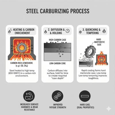
Carburizing introduces carbon into the surface of low‑carbon steels (typically 0.1–0.25% C) at high temperatures (commonly 900–950 °C) where austenite is stable. Carbon diffuses inward from a carbon‑rich environment, creating a high‑carbon case suitable for hardening (quench + temper), while the low‑carbon core remains tough. The resulting case depth (often 0.3–2.0 mm) and carbon gradient are controlled by temperature, time, carbon potential, and steel chemistry. Three main methods are used: pack, gas, and vacuum carburizing.
Parts are packed in sealed boxes with carbonaceous media (charcoal + energizers) and heated to the carburizing temperature. Carbon monoxide generated at the surface provides carbon for diffusion. This method is simple but slower, less controllable (carbon potential), and prone to sooting and variable case depth. Best for small batches, simple geometries, and less stringent case control.
Performed in endothermic or controlled‑atmosphere furnaces with hydrocarbon gases (e.g., methane, propane) and precise carbon potential control via oxygen probes and flow regulation. Offers repeatable case depth, uniformity, and process flexibility (boost/diffuse cycles). Common in high‑volume production of gears and shafts.
Conducted in vacuum furnaces with pulsed hydrocarbon injections at high temperatures (often 950–1050 °C). Enhanced diffusion yields shorter times and deeper cases, with clean surfaces and minimal intergranular oxidation (IGO). Typically followed by high‑pressure gas quenching or oil quench. Preferred for precision components requiring low distortion and clean surfaces.
Process controls: Carbon potential (via oxygen probe), temperature uniformity surveys, timed boost/diffuse cycles, and fixturing to avoid shadowing. Post‑carburize: Quench to form martensitic case (HRC 58–64), then temper to relieve stresses and achieve target hardness. Case depth verification: Microhardness traverses, metallographic etching, and sometimes nital etch for carbon gradient observations.
Common pitfalls: Intergranular oxidation (IGO) in conventional gas furnaces (mitigated by vacuum processes), excessive retained austenite in high‑carbon cases (addressed by sub‑zero treatment or higher temper), distortion from oil quench (minimized by press quench or gas quench), and soot formation affecting uniformity. Material selection: Low‑carbon, low‑alloy case‑hardening grades (e.g., 16MnCr5, 20MnCr5, 8620) provide tough cores and responsive cases.
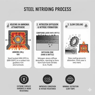
Nitriding introduces nitrogen into steel surfaces at relatively low temperatures (typically 500–580 °C), forming a hard compound layer (ε‑Fe2‑3N, γ′‑Fe4N) and a diffusion zone containing alloy nitrides (Cr, Mo, V, Al). Because nitriding occurs below Ac1, no austenitization or quenching is required, yielding minimal distortion and excellent dimensional stability. The process is well‑suited for alloy steels containing nitride formers (e.g., Nitralloy, 4140/4340 with Cr‑Mo‑V).
Ammonia dissociation supplies nascent nitrogen at the surface; potentials are controlled to tailor compound layer thickness (white layer) and diffusion depth. Cycle times are longer than carburizing due to slower nitrogen diffusion at low temperatures. Provides high surface hardness (often > 1000 HV) and improved wear/fatigue resistance.
Conducted in vacuum with glow discharge; nitrogen ions bombard the surface, enhancing diffusion efficiency and allowing precise control of layer composition and thickness. Advantages include reduced cycle times, lower temperatures, minimal distortion, and ability to mask or selectively treat surfaces. Produces clean surfaces with limited oxidation.
Controls and outcomes: White layer thickness is tuned to application (too thick can be brittle). Diffusion depth depends on time and temperature; alloying raises achievable hardness and stability. Nitrided layers exhibit excellent wear, fatigue, and corrosion resistance (in certain alloys), but the case is thin compared with carburized cases (commonly 0.1–0.7 mm). Pitfalls: Excessive white layer brittleness, porosity in gas nitriding if potential is too high, and limited case depth for very high loads.
Carbonitriding simultaneously enriches the surface with carbon and nitrogen at temperatures typically 700–880 °C (lower than carburizing). Carbon increases surface hardness and wear resistance; nitrogen enhances hardenability of thin sections and improves resistance to softening. The process is advantageous for small parts requiring shallow, hard cases (e.g., fasteners, small gears) with shorter cycle times than carburizing.
Process: Performed in gas atmospheres (e.g., endogas plus ammonia) with controlled carbon and nitrogen potentials. After treatment, parts are often oil quenched and tempered. Outcomes: Case depths commonly 0.1–0.8 mm; high surface hardness; improved response in low‑hardenability steels and thin geometries. Controls: Atmosphere control (C/N potential), temperature uniformity, and dwell time. Pitfalls: Excessive nitrogen can cause retained austenite and lower temper resistance; improper control may yield porous compound layers.
Induction and flame hardening are thermal surface hardening methods that austenitize the surface locally and rapidly, followed by quenching to form a martensitic case. They do not change composition; instead, they exploit localized heating to create a hard case with minimal impact on the core. Case depth is governed by energy input, heating time, and—particularly for induction—the frequency (which controls electromagnetic penetration depth).
An alternating magnetic field induces eddy currents and heats the surface rapidly. High frequency (100–500 kHz) yields shallow cases; medium frequency (10–100 kHz) for moderate depth; low frequency (<10 kHz) for deeper heating. Precise control makes it ideal for shafts, gears, and rails. After reaching austenitizing temperature, immediate quench (spray or polymer) forms martensite. Case depths range ~1–6 mm depending on frequency and dwell.
Oxy‑fuel flame heats the surface to austenitizing temperature; the part is then quenched. Equipment is simpler but control is less precise than induction. Suitable for large or irregular parts where coils are impractical. Case depths and hardness are similar to induction for comparable thermal inputs, but uniformity depends on operator skill.
Material requirements: Medium‑carbon steels (e.g., 1045, 4140) with adequate hardenability respond best; low‑carbon steels may require prior carburizing. Controls: Power, traverse speed, frequency (induction), surface preparation, and immediate quench. Pitfalls: Overheating causing grain growth; decarburization at heated surfaces; distortion if quench is too severe; non‑uniform case depth without tight process control.
Ferritic nitrocarburizing (FNC) introduces nitrogen and carbon at subcritical temperatures (≈ 560–590 °C), forming a thin compound layer (ε/γ′) and a diffusion zone in a ferritic matrix. Because the process occurs below Ac1, it does not involve austenitization or quenching, delivering excellent dimensional stability and low distortion. FNC improves wear resistance, scuffing resistance, fatigue, and, in some cases, corrosion resistance (depending on post‑oxidation).
Carried out in salt bath or gas atmospheres (e.g., ammonia with carbon‑bearing species). Control of nitriding potential and carbon activity determines compound layer thickness and composition. Often followed by controlled cooling and optional post‑oxidation to enhance corrosion resistance.
Uses glow discharge in vacuum to introduce N and C efficiently with minimal environmental impact and precise control. Offers selective treatment and uniform layers on complex geometries.
Outcomes: Compound layers are typically 10–30 µm thick with diffusion zones up to a few hundred microns. Surface hardness rises substantially (often 600–800 HV depending on alloy), while the core properties remain unchanged. Pitfalls: Excessively thick compound layers can be brittle; poor control may yield porous or uneven layers. Applications: Pistons, valves, slides, dies, and wear‑critical surfaces where distortion must be minimal.
Choose the process based on case depth, hardness profile, distortion tolerance, and alloy chemistry: carburizing for deep martensitic cases with tough cores; nitriding for thin, extremely hard layers without quench; carbonitriding for shallow hard cases with improved thin‑section response; induction/flame for localized martensitic cases without compositional change; and FNC for low‑distortion wear and fatigue improvements. Integration with upstream and downstream steps (machining allowances, fixturing, shot‑blasting, tempering, grinding) is necessary to meet final dimensional and performance requirements.
| Process | Typical temperature | Hold time | Cooling method | Primary microstructure | Notes |
|---|---|---|---|---|---|
| Full anneal | Ac3 + 30–50°C (hypoeutectoid); Ac1 + 30–50°C (hypereutectoid) | 1–3 h (section-dependent) | Furnace cool | Coarse pearlite + ferrite | Softest condition; improves machinability |
| Normalizing | Ac3 + 30–50°C | 0.5–2 h | Still air | Fine pearlite + ferrite | Removes banding; improves strength |
| Hardening | Austenitize: 800–950°C (grade-specific) | 0.5–1 h typical | Water, brine, oil, polymer, gas | Martensite (as-quenched) | Risk of distortion/cracks; choose media carefully |
| Tempering | 150–650°C (below Ac1) | 1–3 h typical | Air cool | Tempered martensite | Tune hardness–toughness; avoid embrittlement ranges |
| Austempering | Hold above Ms (e.g., 250–450°C salt bath) | Until bainite completes | Isothermal hold then cool | Bainite | Low distortion; good toughness |
| Martempering | Quench to just above Ms; equalize | Minutes to equalize | Air cool through Ms–Mf | Martensite with reduced stress | Improves dimensional stability |
| Carburizing | 900–950°C | Hours (case depth controlled) | Quench + temper | Hard case; tough core | Low-carbon steels; gas/vacuum methods common |
| Nitriding | 500–580°C | 10–40 h (layer thickness) | No quench | Nitride compound + diffusion layer | Minimal distortion; needs nitride-formers |
| Induction hardening | Surface austenitization (frequency-dependent) | Seconds | Immediate quench | Martensitic case | Case depth via frequency and traverse speed |

Alloying elements profoundly influence the phase transformations, kinetics, and resulting microstructures during heat treatment of steel. They shift critical temperatures, alter TTT/CCT curves, modify Ms/Mf, form carbides or nitrides, and change diffusion rates. The combined effects determine hardenability (depth of martensite formation), resistance to temper embrittlement, secondary hardening potential, distortion tendencies, and achievable surface hardness in thermochemical treatments. Understanding each element’s role helps select appropriate heat treatment schedules and steel grades for targeted performance.
Carbon is the primary strength‑controlling element in steel and the key to martensite formation. Increasing carbon raises as‑quenched hardness and strength by stabilizing supersaturated martensite (greater tetragonality), but it lowers Ms/Mf significantly, increasing retained austenite and brittleness risks. High carbon also increases the propensity for quench cracking and requires careful tempering to manage internal stresses and carbide precipitation. In pearlitic structures, higher carbon yields finer interlamellar spacing and higher hardness; in spheroidized structures, it facilitates cementite formation for machinability.
Manganese is a potent hardenability enhancer that stabilizes austenite and delays diffusional transformations. Mn reduces the pearlite/bainite nose, allowing deeper martensite formation in thicker sections or slower quench media. It also improves deoxidation and hot‑workability, but excessive Mn can exacerbate segregation and banding, affecting uniformity after heat treatment.
Chromium enhances hardenability and wear resistance through both solution strengthening and carbide formation (e.g., M7C3, M23C6). Cr carbides contribute to abrasion resistance in tool steels and increase secondary hardening during tempering. Cr also improves high‑temperature oxidation resistance and corrosion resistance in higher concentrations (stainless steels). In heat treatment, Cr delays pearlite/bainite, enabling oil or gas quenching for thicker sections with reduced distortion.
Nickel primarily improves toughness by stabilizing austenite and refining microstructures. It enhances low‑temperature impact resistance and widens the processing window for quench and temper (less sensitivity to section size). Ni has a modest hardenability effect compared to Cr/Mo but significantly boosts ductility and reduces risk of brittle fracture, making it valuable in structural, pressure vessel, and low‑temperature service steels.
Molybdenum is a powerful hardenability and tempering element. It delays pearlite and bainite formation even more than Cr, enabling deep hardening. Crucially, Mo resists temper embrittlement and supports secondary hardening via fine alloy carbide precipitation during high‑temperature tempering. It also improves creep strength and high‑temperature performance, making it essential in hot‑work tool steels and Cr‑Mo structural grades.
V and Nb are strong carbide/nitride formers that refine grain size by pinning austenite grain boundaries and forming fine precipitates. Their microalloying effect increases strength in normalized or controlled‑rolled conditions and contributes to secondary hardening during tempering in tool steels. In heat treatment, they raise hardenability modestly and improve resistance to softening at tempering temperatures through stable carbides (e.g., VC, NbC).
Silicon strengthens ferrite in solution and influences tempering reactions by suppressing cementite formation at certain tempering ranges, promoting retained fine carbides and improved toughness. Si is also an effective deoxidizer during steelmaking, improving cleanliness. In spring steels and TRIP‑assisted designs, Si helps stabilize bainite and retained austenite during appropriate heat treatments.
Alloying elements rarely act in isolation. Mn+Cr+Mo synergistically increase hardenability, enabling oil/gas quench for large sections. Ni offsets toughness loss from high carbon and strong carbide formers. V/Nb microalloying maintains fine grains despite high‑temperature austenitizing, stabilizing properties. Si supports bainite/retained austenite strategies with Mn in advanced high‑strength steels (AHSS). These interactions dictate the appropriate heat treatment window—temper ranges for secondary hardening, quench severity, and whether sub‑zero treatments are necessary to reduce retained austenite.
Industrial heat treatment demands repeatability, traceability, and safety. Effective practice begins with selecting the right furnace technology and atmosphere for the steel grade and geometry, then verifying process capability through calibration and routine audits. Production lines must integrate loading, fixturing, quenching, tempering, and inspection with documented parameters and controls. Standards provide acceptance criteria and process validation requirements, while safety programs protect people, assets, and the environment.
Conformance frameworks define process setup, qualification, and acceptance. Common requirements include equipment calibration, documented recipes, and verification testing.
Heat treatment routes are tailored to function, load cases, and dimensional tolerances. Below are typical industrial applications with recommended treatments and notes on verification.
| Requirement | Recommended treatment | Typical outcome |
|---|---|---|
| Maximum surface wear resistance with tough core | Carburizing + quench + temper | Hard martensitic case (HRC 58–64), tough core |
| High toughness with moderate hardness | Normalize or austemper | Fine pearlite/bainite, good impact resistance |
| Dimensional stability with high hardness | Martempering + temper | Reduced distortion, tempered martensite |
| Improved machinability of high-carbon steels | Spheroidize anneal | Spheroidized carbides in ferrite; low hardness, easy machining |
| Localized hard wear tracks | Induction hardening | Martensitic case; minimal effect on core |